// In progress · 2025–
Cell characterization bench
A four-wire bench that measures what a pack designer actually needs from a cell — capacity at 1C and at race current, pulse DCIR, and temperature rise to the 60 °C rule limit. Three cells are through it. The Kelvin sense then turned out to be wrong, so every number on this page is provisional.
Status
In progress, and the honest headline is that the results below are provisional. Three cells have been through the full sequence — Reliance RS50, Ampace JP40 and EVE 50PL — before a resistance check on the rig showed the four-wire Kelvin connection was not doing its job. Every internal-resistance number here carries a 5.544 mΩ fixture correction that may or may not be legitimate. The capacity and thermal numbers are unaffected and stand.
This is a two-person program with Yegor Lushpin, feeding cell selection and pack sizing for EV5, next season’s Bearcats Electric Racing car.
The requirement
Pack design starts from cell data, and vendor datasheets are measured under conditions that are not the conditions of an FSAE accumulator. Candidate cells needed measuring on one jig, under one procedure, at currents relevant to the application.
The bench feeds three things downstream:
- Cell selection. Capacity at race current, not at the datasheet’s leisurely rate.
- A pack configuration sweep across series/parallel counts for every candidate cell, scored on weight and voltage.
- Thermal simulation. Per-cell heat rate is the primary boundary condition for the ANSYS model that sets the cooling requirement.
Cells in scope: Molicel P30B, P42A and P45B; EVE 50PL; Ampace JP40; Reliance RS50 and RS60.
Why these four measurements
Each measurement exists because something downstream cannot be decided without it.
| We measure | Because it sets |
|---|---|
| DCIR (R₀) | Sag under load, and heat — I²R is the ANSYS input. A wrong R₀ picks the wrong parallel count. |
| Capacity at rated current | Real usable capacity at race current, which sets how many cells we carry — mass and cost. |
| Temperature rise | Whether we hit the 60 °C rule limit. Every 50 A run so far has been cooling-bound, not energy-bound. |
| R₀ vs SOC and temperature | Tests the tabless claim that IR falls as the cell heats. If true, less heat at temperature, and a different cooling answer. |
The bench
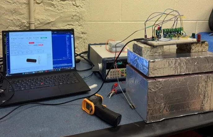
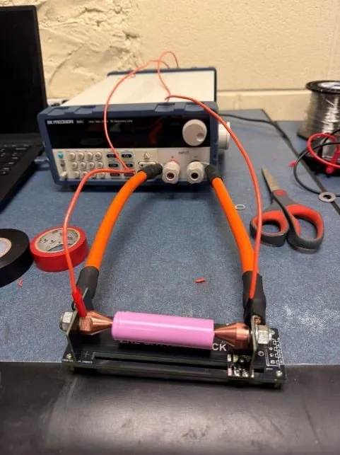
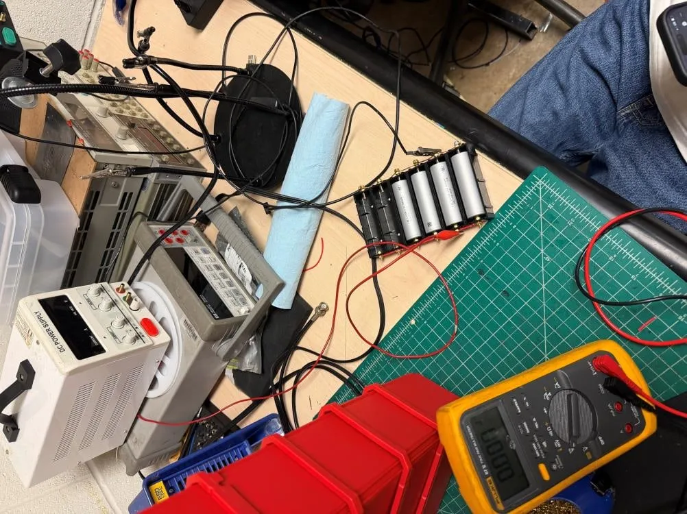
BK Precision 8601 electronic load, so discharge current is programmable and held constant as cell voltage falls. Its Battery-Test mode gives Ah and Wh directly.
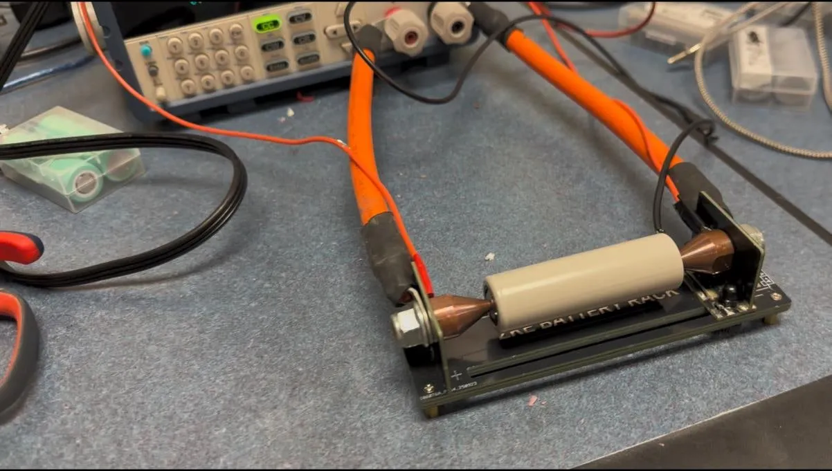
Four-wire (Kelvin) sensing. At these currents, contact and lead resistance are the same order as the internal resistance being measured, so a two-wire measurement returns the fixture as much as the cell. Force and sense paths are separate.
Bolted copper lug clamp replacing the original fixture PCB, for repeatable contact pressure and a defined sense point on the terminal.
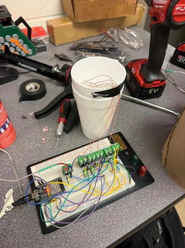
Six type-K thermocouples — five along the cell, one ambient outside the enclosure — on MCP9600 amplifiers read by an ESP32 and streamed over serial. Exposed welded junctions with 1/0.2 mm conductors, chosen for response time: on EV4 the thermocouples were slow enough to low-pass-filter the high-current transients we were trying to see.
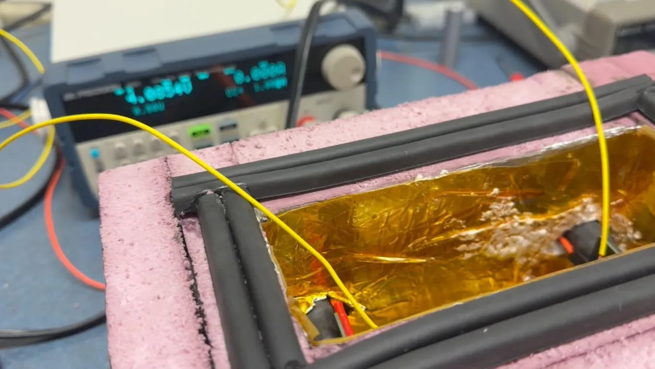
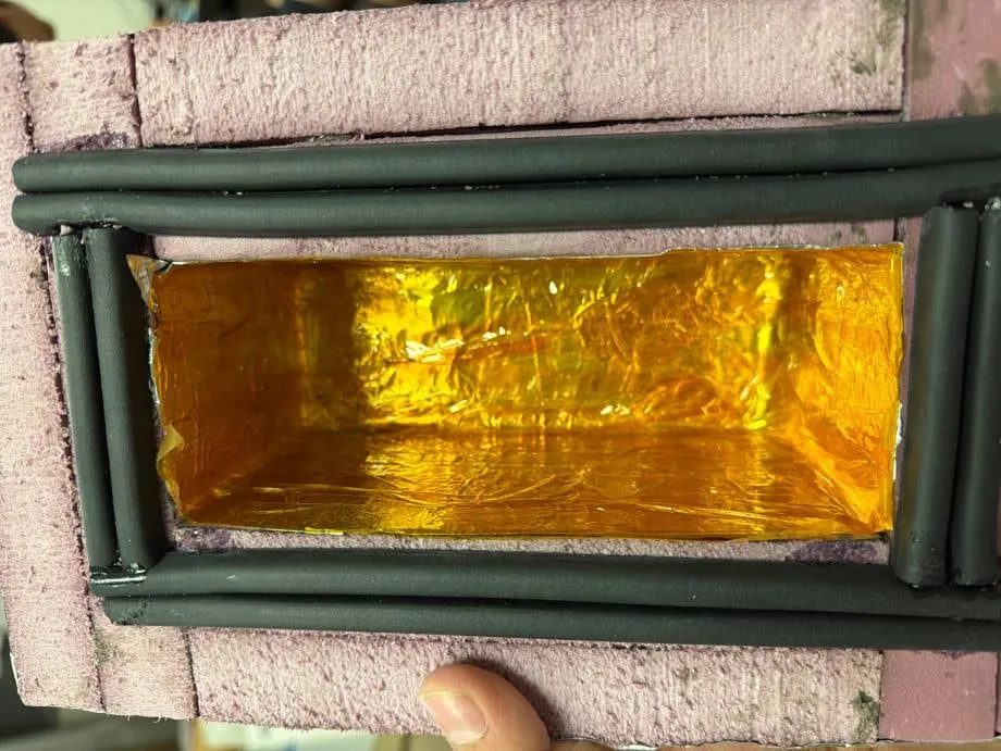
Insulated enclosure with a gasketed lid, held closed by two granite weights, so the thermal environment is the same run to run rather than whatever the room is doing.
Dashboard driving the load and logging per-article, so each physical cell specimen carries its own record.
Procedure
Cells are charged individually on an off-the-shelf four-bay charger, which leaves them at slightly different voltages, then paralleled and topped to 4.2 V on a power supply. They rest 30–60 minutes before any test. Thermocouples go on, the cell goes in the enclosure, contact at both terminals is checked, and the lid and weights go on.
Each test gets a fresh, rested cell:
- Capacity at 1C — discharge to the 2.5 V floor.
- Capacity at rated current — discharge at 10C, the highest rate we were cleared to run, until the 60 °C cutoff.
- Prep for DCIR — discharge at 1C to 50% SOC.
- Pulse DCIR — 1 A for 30 s, 50 A for 10 s, then 1 A for 10 s, simulating a pulse draw. R is taken across the step edge, from the Kelvin sense only, with ΔI = 49 A.
Capacity and SOC come from coulomb counting against the article’s own measured 1C capacity, so each cell is scored against itself rather than against its datasheet.
Rules we run to
The 60 °C cutoff is not an arbitrary safety margin — it is the rule limit, and it is what makes these runs cooling-bound.
- 2.5 V floor, coded into the test so a run terminates on the reading, not on judgement.
- 4.2 V charge limit, room-temperature charging only.
- 60 °C cutoff on every run.
- Two people present for every test, without exception for the rated-current runs.
- Water container and gloves on standby; gloves worn during the rated-current test.
What went wrong
The four-wire Kelvin connection was not working. The first sign was DCIR numbers well clear of what the datasheets claim. To test the rig rather than the cell, we spot-welded a nickel fusible link to a cell, soldered a wire to it as a true terminal-face voltage tap, and measured the drop between that point and the load at 20 A on a precision multimeter. That put 2.772 mΩ in one side of the rig — 5.544 mΩ across the whole thing, which is comparable to the cell resistance we were trying to measure.
The spot-welded tap confirms it. Running the same DCIR at 95% SOC through both paths gave 13.32 mΩ two-wire against 8.7 mΩ four-wire. The 4.6 mΩ delta lands close to the 5.544 mΩ fixture figure, which is the answer we would expect if the fixture resistance is what the Kelvin connection is failing to exclude. The result did not reproduce at 50% SOC, and we do not yet know why.
The verdict is that everything probably has to be re-run with spot-welded sense wires. The open question is whether the existing data survives a flat −5.544 mΩ correction or has to be thrown out — a fixed offset is a reasonable model for a bad sense tap, but only if the tap was bad in the same way on every run.
Calibration and validation
Thermocouples. Ice-bath calibration with TC6 as the in-bath reference. TC6 reads +1.85 °C in a bath that is not truly at zero, which is the positive bias expected from an uncompensated K-type channel. Rather than pretend the bath was a standard, each of TC1–TC5 was trimmed onto TC6 — offsets of −1.15, −0.77, −0.82, −1.02 and −1.02 °C. That buys channel agreement, which is what a five-point profile along one cell actually needs. It does not buy absolute accuracy, and without lab equipment it is as close as we get.
Enclosure heat leak. A sealed bag of ice was weighed, left in the enclosure in its normal hold configuration for 30 minutes with the lid, grommets and penetrations as they sit during a test, then removed, drained, blotted dry of external condensation, and re-weighed. Melted mass gives the steady heat leak through the latent heat of fusion, with the interior pinned at 0 °C while ice remains.
| Quantity | Value | Basis |
|---|---|---|
| Ice melted | 10 g | 140 → 130 g over 30 min |
| Q_leak | 1.86 W | 334 J/g × 10 g / 1800 s |
| Room temperature | 21.2 °C | logged |
| Interior | 0 °C | ice slurry |
| U·A | 0.088 W/K (±~20%) | Q_leak / 21.2 K |
Results
Three cells, one article each. Capacity and thermal figures are direct measurements.
| Cell | 1C capacity | ΔT at 1C | 50 A trip | Fraction of 1C | End state at 50 A |
|---|---|---|---|---|---|
| Reliance RS50 | 5.00 Ah | +9.8 °C | 1.90 Ah | 38% | 60 °C at 3.40 V — not depleted |
| Ampace JP40 | 3.95 Ah | +3.6 °C | 1.89 Ah | 48% | 60 °C, well above the floor |
| EVE 50PL | 5.03 Ah | ~10–11 °C | 1.76 Ah | 35% | 60 °C, well above the floor |
Every one of those runs ended on temperature with most of the cell’s energy still in it. That is the finding that matters: at race current these cells are cooling-limited, not energy-limited, so the accumulator’s cooling design — not its cell count — is what decides how much of the pack is usable.
Resistance, with the 5.544 mΩ fixture correction applied. These are the provisional numbers, and heat rate is Q = I²R₀ at 50 A:
| Cell | Measured R | Corrected R₀ | Heat at 50 A |
|---|---|---|---|
| Reliance RS50 | 11.8 mΩ | 6.3 mΩ | ~15.8 W |
| Ampace JP40 | 12.2 mΩ | 6.7 mΩ | ~16.8 W |
| EVE 50PL | 12.7 mΩ | 7.2 mΩ | ~18.0 W |
JP40’s +3.6 °C at 1C is anomalously low against the other two and needs a re-run to establish whether it is a real difference or a thermocouple contact problem.
Pack and fusing implications
The measured per-cell heat rate is what the ANSYS thermal model consumes. Cell resistance also drives fusing, because FSAE requires every parallel strand to carry its own overcurrent device rated at or below the cell’s continuous rating, and requires the conductor carrying full pack current either to be sized for everything those strand fuses could pass together or to carry a main fuse of its own.
Worked through for a JP40 3p strand at 45 A continuous per cell: strand fuses at 40 A, so the full-pack conductor is sized for 3 × 40 = 120 A, or a main fuse is added instead. If the strands are spot-welded nickel fusible links rather than rated parts, the main fuse drops to 40 A — and the links themselves need manufacturer or test data behind their rating, which our bench does not produce yet.
Where the bench does not match the pack
Two deliberate differences between this rig and the rule set the accumulator is built to, worth stating because they bound what the data can be used for:
- The rules require pack cell temperature to be measured at the negative terminal, or on a busbar within 10 mm of the weld. The bench runs five thermocouples along the cell length instead, because the point here is the thermal profile, not rule compliance. The two need cross-referencing before pack sensor placement is signed off.
- Sensors must be electrically isolated from the cell. The bench already does this with Kapton over the live can, visible in the enclosure photos.
Rule references are against the 2027 FSAE draft released for public comment, which is not valid for competition — every number gets re-checked against the released set.
Next
- Fix the four-wire Kelvin sense — move the taps onto the terminal faces and qualify them.
- Re-baseline the tested articles on corrected R₀ and decide whether the existing data survives the −5.544 mΩ correction.
- Re-run JP40 to resolve the anomalous 1C temperature rise.
- Decide whether pack simulation needs an RC pair for sag fidelity or whether R₀ alone is enough.
- Cross-reference the along-cell thermal profile against negative-terminal sensor placement.
- Generate rated current data for the spot-welded nickel fusible links.