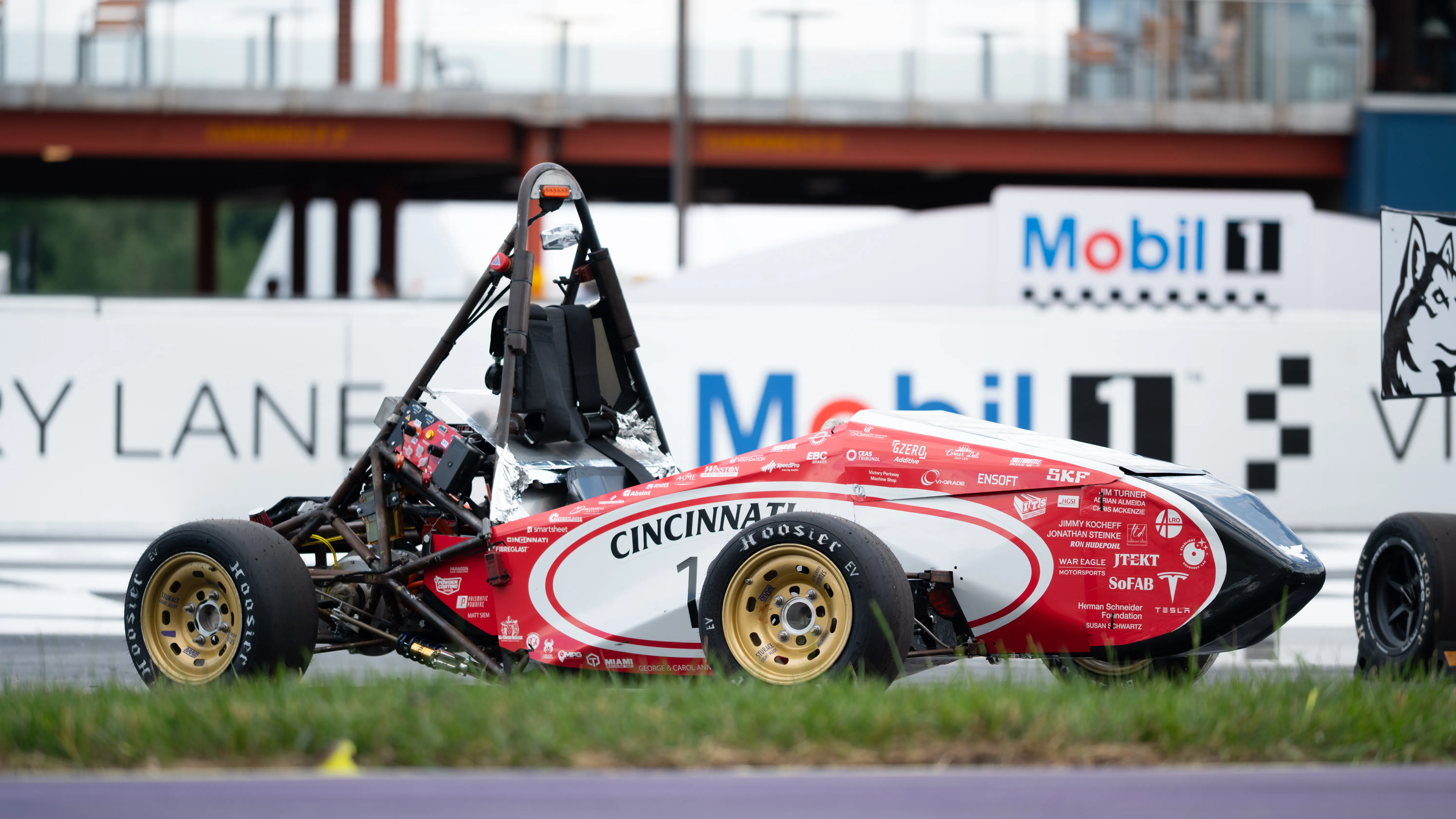
// In progress · 2025–
FSAE data acquisition board
A 4-layer STM32H723 data acquisition board for the Formula SAE electric car — three FDCAN buses, inertial and GPS logging to SD, and an 802.11ah telemetry link. Schematic and layout in Altium; firmware not yet written.
Status
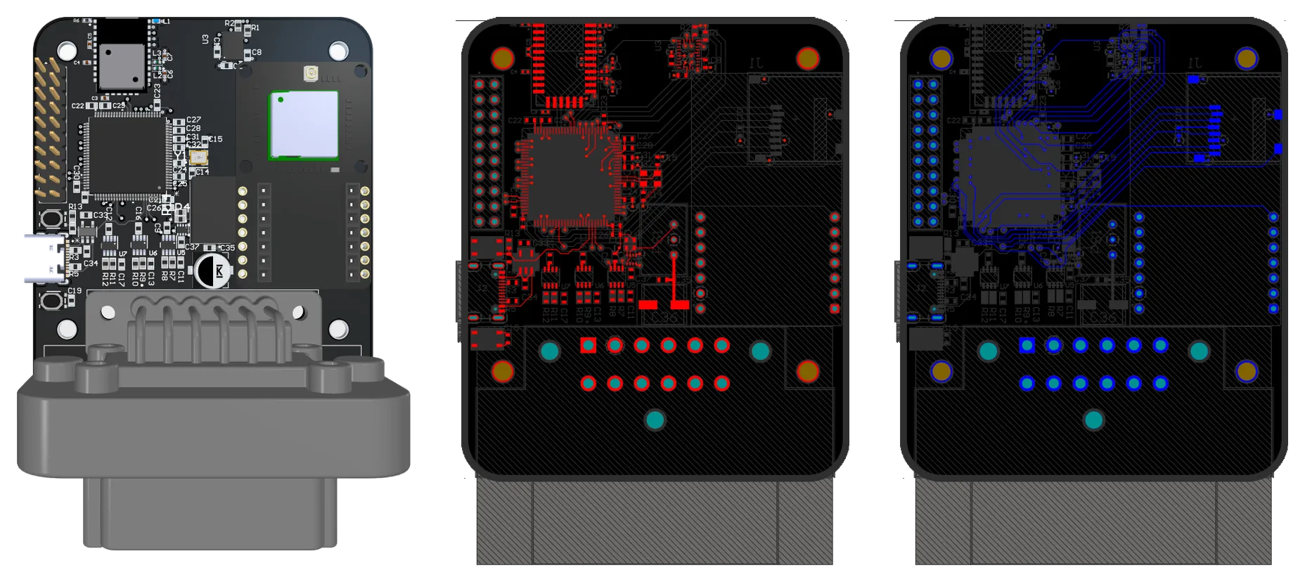
Done so far: the schematic and the 4-layer layout — the board’s routed top and bottom, with the 3D view above. The firmware is just the CubeMX-generated init (clock tree and peripheral setup); no application code yet. It hasn’t been fabricated, so nothing’s been measured and the results section is empty. It’s aimed at next season’s car, EV5.
The requirement
Log inertial, positional and bus data on a common time base, on an FSAE chassis, and stay repairable by students during a competition weekend.
The commercial option is a MoTeC L120 or L180, which is what most teams run. The case for building instead: channel count and bus topology match this car, logging behaviour can be changed between sessions without vendor tooling, and the cost folds into a build the team is doing anyway.
The honest downside: a MoTeC just works. It ships with a warranty, support, and years of use in other cars behind it. Ours has none of that — if it dies during a run there’s no fallback and no one to call, and working out why is on us.
Buying one also hands a lot of hard problems to someone else. Calibration, sealing the connectors, surviving vibration, passing EMC — that’s MoTeC’s job on their box and ours on this one, on a board that isn’t even built yet. And every hour spent on it is an hour not spent on the rest of the car. It only pays off if the board actually gets finished and works.
Design decisions
STM32H723VET6. Three independent FDCAN controllers, native SDMMC, and enough headroom to parse, timestamp and buffer at the same time.
Three FDCAN buses instead of one shared bus, so a high-traffic subsystem cannot delay safety-relevant frames.
BNO085 over SPI. The part runs its own sensor fusion, so the MCU is not spending cycles on an attitude filter.
GPS: Antenova M20050-1. NMEA parsed on the MCU. Timing comes from the PPS output, not from the message contents.
Power: TSR 1-2433E buck, diode-OR’d with a USB-C input so the board runs on the bench with the car unpowered.
Logging: SDMMC in 4-bit mode through FatFS, behind a ring buffer, so a slow card write does not stall acquisition.
Telemetry: 802.11ah HaLow — XIAO ESP32S3 with an FGH100M-H. Lower data rate than conventional Wi-Fi, longer range, which is the tradeoff a trackside link wants.
Service access. USB DFU behind a BOOT0 button, SWD test pads, and a CP2102N-class USB-UART bridge on USART1.
Firmware
Just the setup so far. STM32CubeMX has generated the project — the clock configuration and the peripheral setup for the three FDCAN buses, the SD card, and the sensor interfaces. The logging code that actually reads the buses, timestamps the data and writes it to the card still has to be written.
Test plan
Nothing here is measured yet — the board isn’t built. The plan once it is, in power-on order:
- Power rails first. Verify the
TSR 1-2433Ebuck output and the USB-C diode-OR fallback before any downstream rail is energised. - FDCAN. Bring up traffic independently on each of the three buses.
- Time base. Check the PPS edge against the logged timestamp.
- SD logging. Measure sustained write rate under logging load, to check whether the ring buffer keeps up without stalling acquisition.
This section is replaced with measurements once the board is built.
Artifacts
The 3D view and the routed top and bottom copper are up top. Still to come, once the board is fabricated: photos of the bare and assembled board, the board in the car, and the power-tree and FDCAN schematic sheets.